Installation Procedure for Water Level Controller:
Economy Model Level Controller for (220V AC) Single Phase Pumpset.
Installation of our water level controller system is not a major task and we have made the system in such a way that it is possible to install the system yourself with minimum electrical knowledge or with the help of a simple electrician. The task of installation comprises of two parts, the Power Connection and the Sensing Connection.
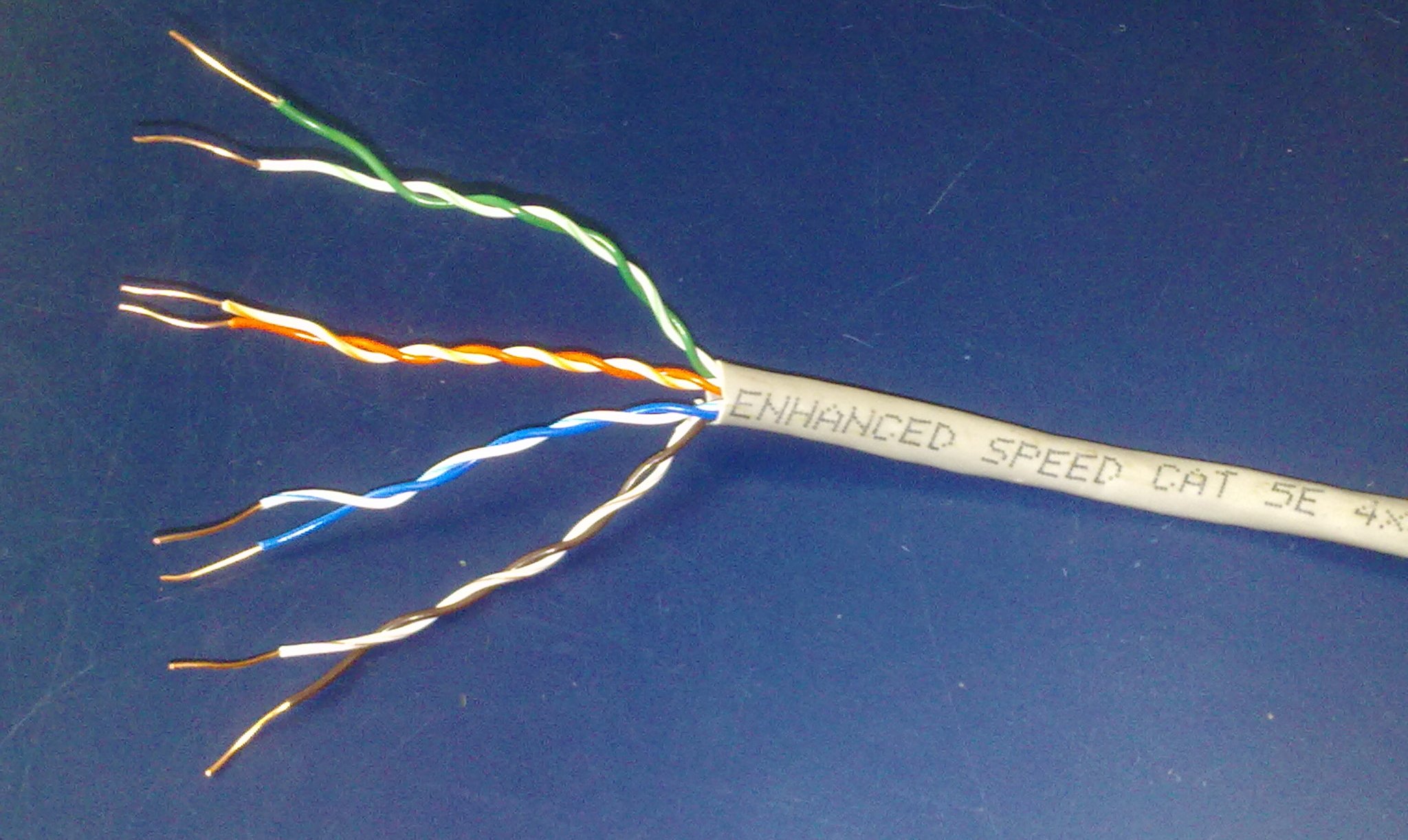
The Power Connection is the connection between the Water Level Controller and your existing Control Switch with which you are presently operating the Pumpset. Sensing Connection includes the cabling of sensing wire, from the Water Level Controller to the Overhead Tank (OH Tank) and again from the Water Level Controller to the Underground Sump (UG Sump). For doing this 2 pair good quality telephone wire or 4 core multistrand wire can be used. For a long life of cable, 4 pair CAT 5e Communication Cable can be used, which is advised. After cabling, making the level sensing arrangement in the water tanks and Sensing connection of the sensing cable to the Water Level Controller.
Tools required for Installation:
- 4 Core cable as per requirement. Take a rough estimate of cable length from the pump control switch location to the OH Tank and again from the pump control switch to the UG Sump.
- One length of 3/4th or 1 inch dia. PVC Electrical Pipe for sensor arrangement in the tanks.
- Multi strand 1.5 Sq.mm. Copper Power cable of about 2 to 6 meters as per requirement for power connection.
- Line Tester.
- Insulation Tape, necessary screws and wooden gattas pieces for mounting controller unit on the wall.
- Cutting Pliers or Nose Pliers.
- Simple Hammer-Jumper set or Drill Gun to mount the Level Controller to wall or to wooden board.

Sensing Cable Connection to Water Level Controller.
STEP 1. The sensing wires comprises of two bunches of coloured wires in the bottom of the unit, one bunch of four wires for sump Tank or lower Tank and another bunch of Three wires for upper Tank or OH Tank.
STEP 2. Do complete sensing wiring from Water Level Controller to Overhead Tank and Water Level Controller to Underground Sump / Well and leave about 1-2 Meter of wire extra in the tanks.
STEP 3. To connect the sensing wires of OH Tank and Sump Tank / Well to the Water Level Controller unit, simply twist the wires to the respective wires of Water Level Controller unit as per the below table. Slide the PVC sleeve provided over the twisted joint completely. The advantage of having loose sensing wire over the sensing terminal block is that, loose contacts are avoided and testing of the controller functions can be done easily by shorting the sensing wires in the controller itself directly.
STEP 4. OH Tank Sensing Connection with bunch of Three wires: -
| Description | Colour of Wire in Sensing Cable | Colour of Wire in Controller |
| PUMP OFF. | Orange | Red. |
| PUMP ON. | Green | Green |
| SIGNAL COMMON. | Blue | Black |
STEP 5. UG Sump Sensing Connection with bunch of Four wires:
| Description | Colour of Wire in Sensing Cable | Colour of Wire in Controller |
| TANK FULL. | Brown | Orange. |
| PUMP ON. | Orange | Red. |
| PUMP OFF | Green | Green |
| SIGNAL COMMON. | Blue | Black |
Sensor Probes Connections and Sensors Level setting in Overhead Tank and Underground Sump.

Overhead Tank Sensing Procedure:
STEP 1. Do the sensing wire cabling from the level controller to overhead tank and leave 1.5 to 2 meter extra cable near overhead tank.
STEP 2. To give the Sensing connection in the Overhead Tank, initially decide the levels at which the pump has to switch ON and switch OFF. As usual procedure, ON Level can be 50% of tank capacity and OFF Level can be 2 to 3 inches less than 100% capacity of Tank (Overflow Level).
STEP 3. Take an electrical PVC pipe of 3/4th inch or 1 inch which is commonly available. Cut the pipe about 2 inch less than the height of the tank so that pipe can be hanged vertically inside the tank.
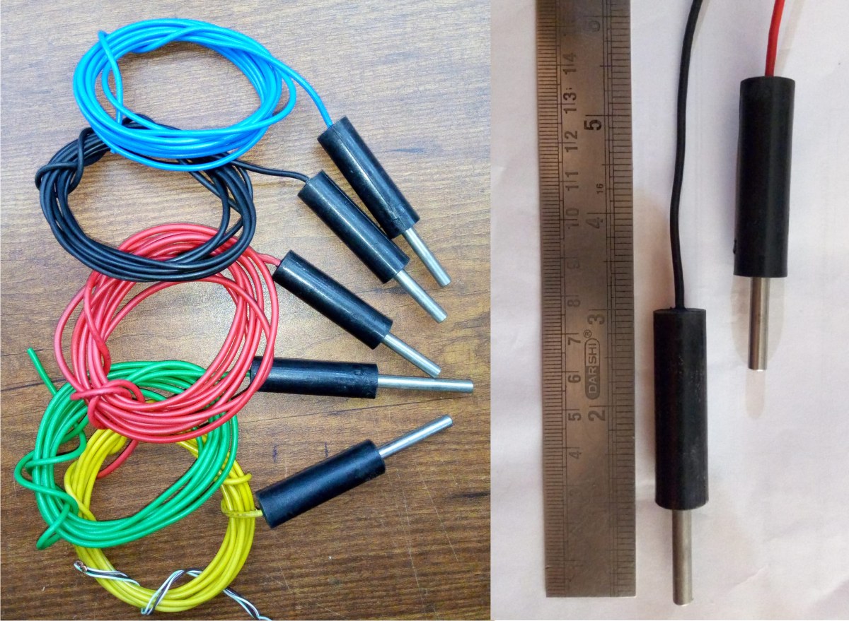
STEP 4. The Level Controller comes with Plastic Molded SS Sensor Probes, with 1 Met. length of wire, which are suitable to fix to the PVC Pipe with the help of Cable Ties (which will be supplied).
STEP 5. Insert the Cable Tie to the sensor probes and fix it to the PVC Pipe as shown in the Photo at required ON and OFF levels to the PVC pipe.
STEP 6. Terminate the 4 Pair sensing cable which is wired from Level Controller to the OH Tank and the wires of the Sensing Probes outside the OH Tank as mentioned in above table.
STEP 4. Fix the sensing wires to the top of the PVC pipe with insulation tape with the regular insulation tape.
STEP 5. Make the loop of the sensing wire, to hang the sensing arrangement to the top portion of the tank with the help of a hook or nail.
STEP 6. The sensing arrangement should be away from the wall of the tank and also should be away from the water falling into the tank.
STEP 7. Connect the sensing wires coming from controllers to the wires of plastic molded sensor wires as follows and insulate with insulation tape. Keep all three joints seperately outside the water tank.
- Set the level of Common sensor (Black wire) at the bottom of the Tank.
- Set the level of Pump ON sensor (Green wire) at the Half level of the Tank.
- Set the level of Pump OFF sensor (Red wire) at the Full level of the Tank.
Underground Sump Sensing Procedure.

STEP 1. Do the sense wire cabling from the level controller to underground sump and leave 1.5 to 2 meter extra cable near underground sump.
STEP 2. To give the Sensing connection in the underground sump, initially decide the levels at which the pump has to switch ON and switch OFF. As usual procedure, ON Level can be 30% of tank capacity and OFF Level can be 4 to 5 inches above the Foot valve of the suction pipe of Pumpset.
STEP 3. Take an electrical PVC pipe of 3/4th inch or 1 inch which is commonly available. Cut the pipe about 12 inches less than the height of the sump so that pipe can be hanged vertically inside the sump.
STEP 4. The Level Controller comes with Plastic Molded SS Sensor Probes, with 1.5 Met. length of wire, which are suitable to fix to the PVC Pipe with the help of Cable Ties (which will be supplied).
STEP 5. Insert the Cable Tie to the sensor probes and fix it to the PVC Pipe as shown in the Photo at required ON and OFF levels to the PVC pipe.
STEP 6. Terminate the 4 Pair sensing cable which is wired from Level Controller to the UG Sump and the wires of the Sensing Probes and connect them as mentioned below and insulate.
STEP 7. Fix the sensing wires to the top of the PVC pipe with insulation tape with the regular insulation tape.
STEP 8. Make the loop of the sensing wire, to hang the sensing arrangement to the top portion of the sump with the help of a hook or nail.
STEP 9. The sensing arrangement should be away from the wall of the tank and also should be away from the water falling into the tank.
STEP 10. Sleeve the sensing wires and connect the other wire end of SS sensor probe in the following order: -
- Set the level of Common sensor (Blue wire) at the bottom of the Sump.
- Set the level of Pump OFF sensor (Green wire) at the bottom of the Sump at about 4 to 5 inches above Foot Valve level in the Sump.
- Set the level of Pump ON sensor (Orange wire) approximately at One Foot above the Sump medium sensor in the Sump.
- Set the level of Sump Full sensor (Brown wire) at the maximum level of UG sump.
Important: The Sensing wire from the unit to OH Tank and unit to UG Sump / Well should be a one-piece wire and there should be absolutely no joints in these Sensing wires and these wires should not be damaged in any way. Unit will not operate correctly in these cases. Continuity of wire should be checked before wire is laid. This sensing wire can be put inside PVC pipe throughout for extra protection.

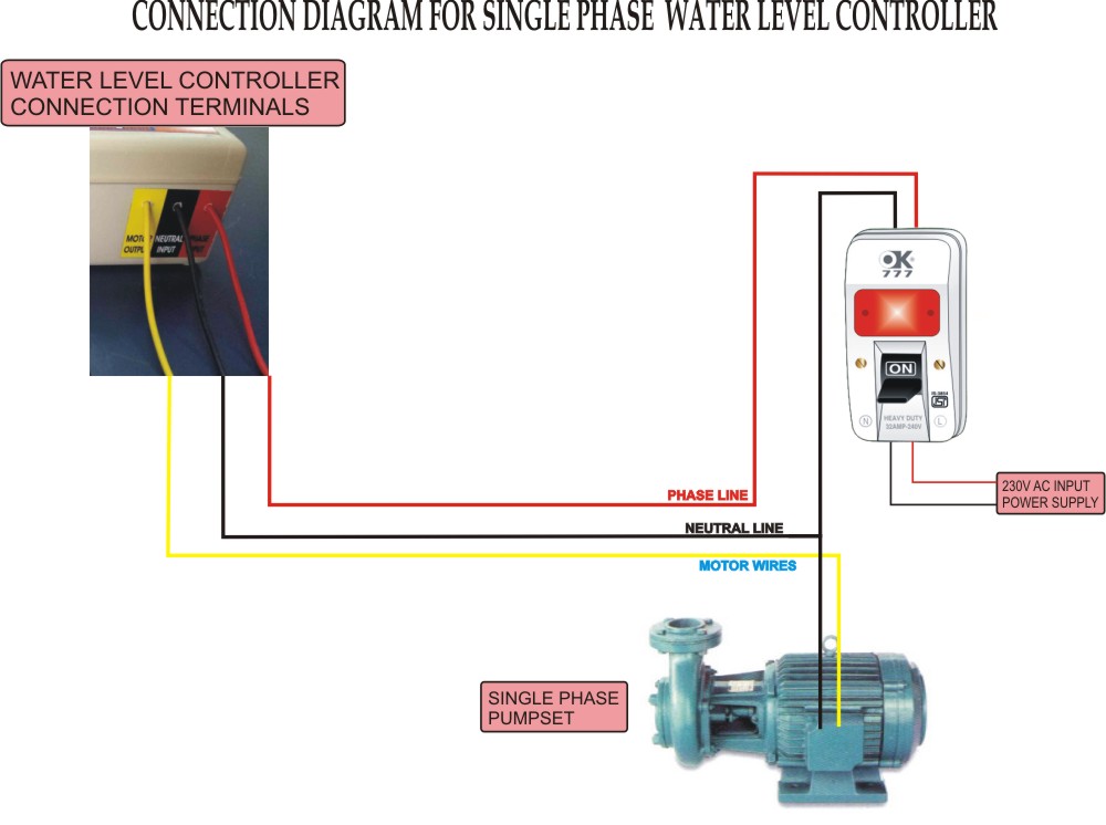
Power Connection from the (220V AC) Single Phase Starter / MCB / DP Switch to the Water Level Controller.
STEP 1. Isolate the Main Power Supply before the Power Connection Procedure and remove the top cover of Starter or Switch.
STEP 2. Identify Phase & Neutral wire in the Starter with "LINE TESTER" after switching ON the power supply.
STEP 3. Now switch OFF the Mains and remove the Phase terminal of the starter or DP switch.
STEP 4. Identify the Phase Terminal on the bottom of Water Level Controller which is Red Wire Neutral Terminal which is Black Wire.
STEP 5. Connect a wire from Phase terminal of Water Level Controller (Red Wire) to the Phase terminal of the starter as shown in diagram. and insulate with insulation tape.
STEP 6. Connect a wire from Neutral terminal of Water Level Controller (Black Wire) to the Neutral terminal of the starter as shown in diagram. and insulate with insulation tape.
STEP 7. Connect the Output Terminal of Water Level Controller (Yellow Wire) to the removed motor wire of the starter as shown in diagram. and insulate with insulation tape.
STEP 8. Now the power connection is completed.
STEP 9. Put the Auto/Manual Switch of Level Controller to Manual Mode, switch ON the Mains to Confirm that the motor in working in Manual Mode.
STEP 10. Now put the Auto/Manual Switch of Level Controller to Auto Mode. "Power ON" LED should glow. Some times if the water level is less in OH tank, Pump may switch ON after a delay of 8 seconds.
Testing of Complete Automatic System.
OH Tank testing procedure:
STEP 1. Immerse all four UG sump sensing probes inside the UG sump water.
STEP 2. Then start testing the OH Tank function. This can be done by immersing and lifting of the sensor arrangement in the OH Tank water.
STEP 3. In OH Tank, lift slowly both Pump ON sensor and Pump OFF sensor above water level. Now the pump should start pumping after a delay of 8 seconds.
STEP 4. Now immerse only Pump ON sensor inside the water, now OH Tank Medium LED will indicate and pump should continue to run.
STEP 5. Now immerse Pump OFF sensor also inside the water, now OH Tank High LED will indicate and pump should switch OFF immediately after a delay of 8 seconds.
STEP 6. Now lift only Pump OFF sensor from the water, now OH Tank High LED will switch off and Pump should remain OFF.
STEP 7. Now lift Pump ON sensor also from the water, now Pump should switch ON again after a delay of 8 seconds.
STEP 8. Repeat the steps from STEP 3 to STEP 7 for four to five times to ensure the correct operations.
STEP 9. Now OH Tank testing is completed.
UG Sump testing procedure:
STEP 1. Keep the OH Tank ON and OFF sensors outside the water, now the pump will switch ON after a delay of 8 seconds.
STEP 2. In UG sump, slowly lift the Sump Full sensor (topmost sensor) above the water. The Sump Full LED will switch off.
STEP 3. Now, slowly lift the Sump High sensor above the water, now Sump High LED will switch off but the pump will remain ON.
STEP 3. Again slowly lift the Sump Low sensor also, above the water, now Sump Low LED will switch off and pump will switched OFF immediately.
STEP 4. Now slowly dip the Sump Low sensor inside the water, now Sump Low LED will glow but the Pump will remain OFF.
STEP 5. Again slowly dip the Sump High sensor also inside the water, now Sump High LED will glow and the Pump will switch ON after a delay of 8 seconds.
STEP 6. Repeat the steps from STEP 2 to STEP 5 for four to five times to ensure the correct operations.
STEP 7. Now UG sump testing is completed. Suspend both UG sump and OH tank sensing arrangements in proper position and tie it to ensure the same.
STEP 8. As a final step fold and keep all the wires neatly and put insulation tape if required.