Installation Procedure for 10 Level Digital Water Level Indicator:
10 Level Digital Water Level Indicator Installation details.
Installation of our water level indicator system is a very simple task and we have made the system in such a way that it is possible to install the system yourself with minimum electrical knowledge or with the help of a simple electrician. The task of installation comprises of two parts, the Power Connection and the Sensing Connection.
The Power Connection to the Water Level Indicator is nothing but supplying single phase power (230V AC) to the Level Indicator. Sensing Connection includes the cabling of sensing wire, i.e., 12 Core Multistrand Cable from the Water Level Indicator to the Overhead Tank (OH Tank) or to the Underground Sump (UG Sump), which ever tank required to have level indication. After cabling, making the level sensing arrangement in the water tanks and Sensing connection of the sensing cable to the Water Level Indicator.
Tools required for Installation:
- 4 Pair CAT 5e Communication cable as per requirement. Take a rough estimate of cable length from the pump control switch location to the OH Tank and again from the pump control switch to the UG Sump (for Bore well, cable is required only for the OH tank).
- One length of 3/4th or 1 inch dia. PVC Electrical Pipe for sensor arrangement in the tanks.
- Multi strand 1.5 Sq.mm. Copper Power cable of about 2 to 6 meters as per requirement for Power Supply.
- Line Tester.
- Insulation Tape, necessary screws and wooden gattas pieces for mounting indicator unit on the wall.
- Cutting Pliers or Nose Pliers.
- Simple Hammer-Jumper set or Drill Gun to mount the Level Indicator to wall or to wooden board.
As the Level Indicator is independent of the pumpset location, choose the position of mounting of the level indicator in such a way that it is easier to have the wiring done from the OH tank to the indicator and it is easily visible to the user or the operator in the Pump Room and is close to the Single Phase Power Supply. The unit can be easily mounted on the wall with Three screws, Two on top with Keyway hole and one at the bottom.

Sensing Cable Connection to Water Level Indicator.
STEP 1. The sensing connection has a 12 way industrial type terminal block with complete labeling of connection details.
STEP 2. Do complete sensing wiring from Water Level Indicator to Water Storage Tank.
STEP 3. To connect the sensing wires of Water Tank, to the Water Level Indicator unit, simply connect the respective terminal block of the Indicator unit as per the below table.
STEP 4. Water Tank Sensing Connection to the Terminal Block: -
| Description | Colour of Wire in Sensing Cable | Indicator Terminal Name |
| TANK 100%. | Dark Brown | 100% |
| TANK 90%. | White | 90% |
| TANK 80%. | Grey | 80% |
| TANK 70%. | Voilet | 70% |
| TANK 60%. | Blue | 60% |
| TANK 50% | Green | 50% |
| TANK 40%. | Yellow | 40% |
| TANK 30%. | Orange | 30% |
| TANK 20%. | Red | 20% |
| TANK 10%. | Brown | 10% |
| Low Buzzer Selection. | Jumper wire piece to 10% / 20% / 30% or any required level | SEL |
| COMMON. | Black | COM |
The Low Buzzer Selection pin has to be connected to the terminal of 10% or 20% or 30% or which ever is chosen to have low buzzer to come, so that required action can be taken to fill the tank.A small piece of wire has to be put between the SEL terminal and the required level terminal so that the selection is acheived. If Low buzzer is not required, then the SEL terminal has to be connected with COM terminal.
Sensor Probes Connections and Sensors Level setting in Overhead Tank.
STEP 1. Do the 12 Core Multistrand Cable cabling from the level indicator to overhead tank and leave 1.5 to 2 meter extra cable near overhead tank.
STEP 2. Take an electrical PVC pipe of 3/4th inch or 1 inch which is commonly available. Cut the pipe about 2 inch less than the height of the tank so that pipe can be hanged vertically inside the tank.
STEP 3. To give the Sensing connection in the Overhead Tank, initially decide the levels, where sensors have to be fixed, by deviding the tank into five parts approximately and mark the level at the PVC pipe.
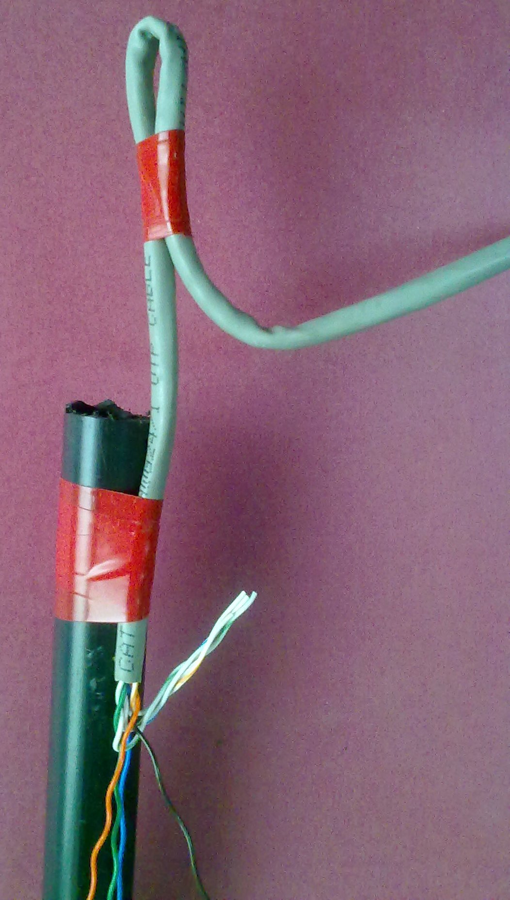
STEP 4. Sleeve the outer grey sleeve of the sensing wire upto the height of the PVC pipe. Fix the grey portion of the wire to the top of the PVC pipe with insulation tape as shown in the Photo with the regular insulation tape.
STEP 5. Make the loop of the sensing wire, as shown in the Photo to hang the sensing arrangement to the top portion of the tank with the help of a hook or nail.
STEP 6. The sensing arrangement should be away from the wall of the tank and also should be away from the water falling into the tank.
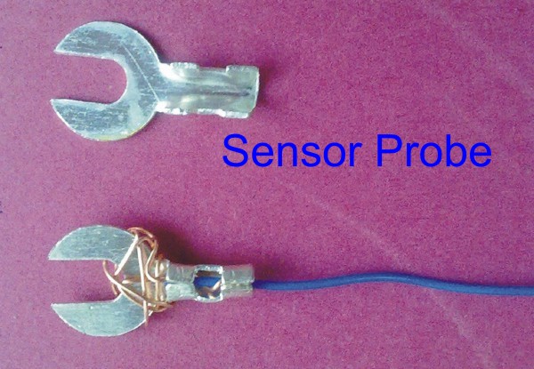
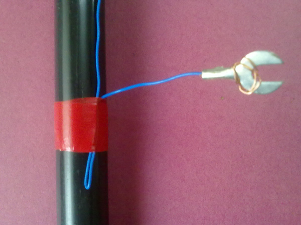
STEP 7. Sleeve below mentioned wires for about 3 to 4 inch, twist the sleeved wire around the sensors provided and crimp the sensors to the end of those wires as shown in the Photo. Now fix the sensors at different levels of the pipe as per the levels decided, with insulation tape as shown in the Photo in the following order: -
- Set the level of Common sensor (Black wire) at the bottom of the Tank.
- Set the level of 10% sensor (Brown wire) at the 20% level of the Tank.
- Set the level of 20% sensor (Red wire) at the 40% level of the Tank.
- Set the level of 30% sensor (Orange wire) at the 80% level of the Tank.
- Set the level of 40% sensor (Yellow wire) at the 80% level of the Tank.
- Set the level of 50% sensor (Green wire) at the Full level of the Tank.
- Set the level of 60% sensor (Blue wire) at the 20% level of the Tank.
- Set the level of 70% sensor (Voilet wire) at the 40% level of the Tank.
- Set the level of 80% sensor (Grey wire) at the 80% level of the Tank.
- Set the level of 90% sensor (White wire) at the 80% level of the Tank.
- Set the level of 100% sensor (Dark Brown wire) at the Full level of the Tank.
Important: The Sensing wire from the unit to the indicator unit should be a one-piece wire and there should be absolutely no joints in these Sensing wires and these wires should not be damaged in any way. Unit will not operate correctly in these cases. Continuity of wire should be checked before wire is laid. This sensing wire can be put inside PVC pipe throughout for extra protection.
Power Connection from the (220V AC) Water Level Indicator.
The Water Level Indicator comes with 2 Way Terminal Block. Connect Phase and Neutral as inidcated in the lable.
Testing of Complete Indication System.
STEP 1. Switch ON the Indicator and go to Overhead tank for testing.
STEP 2. It is convineant to test the indicator by having cell phone communication from the OH Tank to Indicator Unit.
STEP 3. Lift the sensing arrangement completely above the water - Indicator should not show 00.
STEP 4. Now immerse common and 10% sensor probe inside water - 10% indication will get displayed.
STEP 5. Now immerse 20% sensor probe inside water - 20% indication will get displayed.
STEP 6. Now immerse 30% sensor probe inside water - 30% indication will get displayed.
STEP 7. Now immerse 40% sensor probe inside water - 40% indication will get displayed.
STEP 8. Like this complete indications can be checked upto 100%.
STEP 9. In the same way sensors can be slowly raised also to check the level indications droping and ensure the correct operations.
STEP 11. Also make sure that the buzzer comes when 100% level is reached. Press Mute Button to silence the sound.
STEP 12. In the same way check the low buzzer function also at the set low level.